Spin-polarized Scanning Tunneling Microscopy (SP-STM)
SP-STM is STM performed with a magnetic tip. When both surface and tip are magnetic, the imbalance of spin-up and spin-down electrons around the Fermi level (see Figure 1) leads to an additional contribution to the tunnel current, which depends on the angle of tip and local surface magnetization, known as TMR effect. In an STM experiment this combines ultimate resolution with spin-sensitivity, which allows to investigate magnetic phenomena of conducting samples down to the atomic length scale. Magnetic tips can be made from bulk material, or prepared by coating non-magnetic tips with a thin film of magnetic material. Ferromagnetic materials like Fe as well as antiferromagnets such as Cr are used for tips. Spin-polarized tips can also be obtained by picking up magnetic material from the surface. The choice of magnetic tip depends on the designated experiment. As a rule of thumb, samples which do not react to external magnetic fields are investigated with ferromagnetic tips while antiferromagnetic tips are employed on magnetically soft materials. With this approach the magnetostatic interaction between tip and sample system is minimized and in addition the magnetization of one electrode can be controlled by an external field while the other stays unchanged.
The most common measurement modes of SP-STM are constant current images (see Figure 2), maps of the differential conductance (dI/dU maps, Figure 3) and dI/dU(U) spectroscopy (Figure 4). Constant current imaging is ideally suited for atomic scale spin textures like antiferromagnets or non-collinear magnetic states. Typically low bias voltages are used to limit the number of contributing electronic states. dI/dU maps are a good choice for larger magnetic structures or when working on stepped surfaces. The dI/dU signal is measured by lock-in technique, adding a small modulation to the tunnel bias voltage. Here the magnetic contrast can be optimized by selecting highly spin-polarized electronic states at specific energies, but the scan speed is now limited by the lock-in time constant. Spin-polarized spectroscopy gives access to the energy dependence of the spin-polarization. Recently, the combination of SP-STM and atom manipulation has offered the exciting possibility to investigate magnetic properties of artificial structures, which can be built atom by atom with a high degree of flexibility and control (see Figure 5).
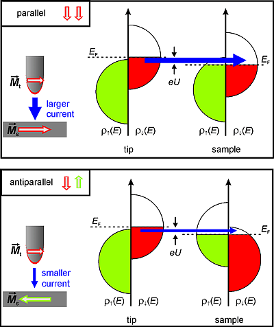 Figure 1: Tunnel magneto-resistance effect (TMR): The tunnel current between two magnetic electrodes depends on the angle between their magnetization directions.
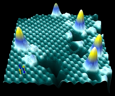 Figure 2: Constant current image (topography) of an antiferromagnetic atomic layer iron on W(001) with defects and adatoms. Depending on their spin direction (up or down, see arrows in image), the Fe atoms appear as protrusion or indentation in constant current images (measurement parameters: T = 8 K, I = 1 nA, U = -50 mV, image size: 10x10 nm2)
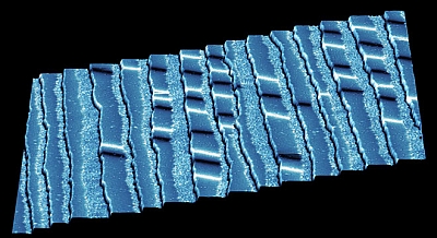 Figure 3: Differential conductance map (dI/dU): Constant current image, colorized with simultaneously measured dI/dU signal: 1.5 atomic layers of Fe on W(110). With an in-plane sensitive tip domain walls in the double layer wires can be observed and discriminated by their magnetization direction (measurement parameters: T = 14 K, I = 300 pA, U = -100 mV; Lock-in time constant: 1 ms, frequency: 1777 Hz, bias modulation: 30 mV, image size: 300x300 nm2)
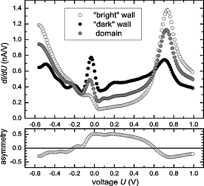
Figure 4: Spin-polarized spectroscopy of two atomic layers Fe/W(110). The asymmetry shown below reflects the energy dependent spin-polarization of the tunnel junction, which in general contains contributions from both tip and surface.
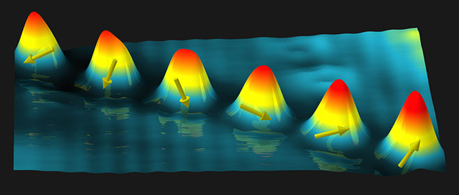 Figure 5: Imaging and manipulation of atomic spins: Constant current image of Co atoms on Mn/W(110). The electron density distribution around the atoms – when probed with a spin-polarized tip - depends on the atoms spin direction. (T = 10 K, images size: 8x5 nm2)
